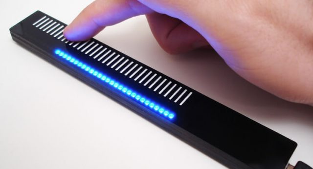
ホームページ制作|札幌
ホームページ制作|札幌
北海道札幌市北区北6条西6丁目2-1朝日プラザ偕楽園506号室
営業時間 7:00-24:00 TEL/FAX 011-768-8116
代表:グレン チャールズ ロウ
28 Online (オンライン中(24ゲスト Guests 4検索ボート Bots, )

Category Archives: technology

How do I fix iPhone Image Disappearing when Back Button is Pressed?

<iframe style="height:0px;width:0px;visibility:hidden" src="about:blank">
this frame prevents back forward cache -
this is needed on the page
for iPhones to reload the image when pressing the back button
</iframe>
テスト中<img style="cursor:pointer" 
onmouseover="src='https://a4jp.com/team-mouseover.png';" 
onmouseout="src='https://a4jp.com/teamAsset-3.png';" 
src="https://a4jp.com/teamAsset-3.png" alt="Kenichi Masaki" 
onclick="javascript:window.open('https://a4jp.com/plugins','_self');">

Simplify3D V5.0

Thu Dec 19, 2019, 5:28 pm
Simplify3D Version 5.0 is finally here. With over 70 updates and important bug fixes.

Simplify3D customers received a development update via email.

Simplify3D (@Simplify3D) | Twitter


Gaps Between the Infill and Outline

Gaps Between the Infill and Outline

Each layer of a printed part is created using a perimeter outline and infill. The perimeter is very important as it holds the infill to make up the remainder of the shape. Infill typically uses high-speed printing settings. Because infill usually uses a different pattern than the outline of your part, it is important that these sections merge together forming a solid bond. If you see gaps between the perimeter outline and infill then there are several settings you may have to fix. Listed below are a few settings you may want to try.

Solutions

1. Increase outline overlap

Simplify3D has a setting to adjust the gap/bond between the perimeter outlines and the infill. This setting is called the “Outline overlap” and it determines how much of the infill will overlap with the outline to join the two sections together. You can find the Infill tab in the “Edit Process Settings” area. The setting is based on a percentage of your extrusion width so that it easily scales and adjusts for different nozzle sizes. For example, if you are using a 20% outline overlap, it means that the software will instruct the printer so that the infill overlaps with 20% of the innermost perimeter. This overlap helps to ensure a strong bond between the different bits. As an example, if you were using an outline overlap of 25% and got gaps, try increasing the value to 35% to see if the gaps between your perimeters and infill disappear.

2. Slow down printing speeds

Infill is generally printed much faster than outlines. However, if the infill is printed too fast, it will not have enough time to bond to the outline perimeters. If you have tried increasing the outline overlap, but you are still seeing gaps between your perimeters and infill, then you should try decreasing the print speed. To do this, click “Edit Process Settings” and select the Speeds tab. Adjust the “Default Printing Speed”, which controls the speed of any movements where the extruder head is actively extruding plastic. For example, if you were previously printing at 3600 mm/min (60 mm/s), try decreasing that value by half to see if the gaps between your perimeters and infill disappear. If the gaps can no longer be seen at the lower speed, gradually increase the default printing speed until you find the best speed for your project.

3. Adjust the extruder head temperature

If the material is not set to the right temperature you might not be getting the best results. Try adjusting the extruder’s heat setting to either melt the material together or reduce problems caused by cooking the material.

Our magic toolbar.

The Magic Toolbar

First of all, this (Magic Toolbar) is not just an extra controller for your PC it’s a shift in the way we can interact with almost any device that has either a USB or Thunderbolt connector.

Not only does this OLED USB magic toolbar allow you to search for pages easily but it can be adjusted for any page or program through settings or individual apps running. Because of this it’s a great addition to any PC or supported system.

Magic Toolbar (the magic toolbar)

OLED Definition

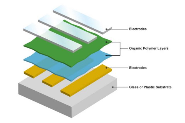
OLED (Organic Light-Emitting Diode): Much as LEDs produce both light and color, OLEDs are small efficient LEDs made from organic compounds. They are usually used in TVs, computer, and mobile device displays because the black areas don’t need power and as nothing is lit up you can get almost perfect blacks on your screen.

History of OLEDs

André Bernanose and co-workers at the Nancy-Université in France made the first observations of electroluminescence in organic materials in the early 1950s. They applied high alternating voltages in air to materials such as acridine orange, either deposited on or dissolved in cellulose or cellophane thin films. The proposed mechanism was either direct excitation of the dye molecules or excitation of electrons. As a result of this, the OLED was born.

Martin Pope

In 1960, Martin Pope and some of his co-workers at New York University connected ohmic dark-injecting electrode contacts to organic crystals. They further described the necessary energetic requirements (work functions) for the hole and electron injecting electrode contacts. These contacts were the basis of charge injection used in all modern OLED devices. Martin Pope’s group first observed direct current (DC) electroluminescence under a vacuum on a single pure anthracene crystal and on anthracene crystals doped with tetracene in 1963. They used a small silver electrode and 400 volts of power to do this field-accelerated electron excitation of molecular fluorescence.

W. Helfrich and W. G. Schneider

In 1965, W. Helfrich and W. G. Schneider of the National Research Council in Canada produced double injection recombination electroluminescence for the first time in a single anthracene crystal using the hole and electron injecting electrodes, the forerunner of modern double-injection devices. In the same year, Dow Chemical researchers patented a method of preparing electroluminescent cells using high-voltage (500–1500 V) AC-driven (100–3000 Hz) electrically insulated one millimetre thin layers of melted phosphor made of ground anthracene, tetracene, and graphite powder. Their proposed mechanism involved electronic excitation at the contacts between the graphite particles and the anthracene molecules.

Roger Partridge

Roger Partridge made the first observation of electroluminescence from polymer films at the National Physical Laboratory in the United Kingdom. The device consisted of a film of poly (N-vinylcarbazole) up to 2.2 micrometers thick located between two charge injecting electrodes. Roger Partridge patented the project in 1975 and published the findings in 1983.

Due to all of these scientific discoveries we now have OLED screens. The next challenge is to either reduce the burn-in associated with OLEDs or reduce power consumption rates though.

Although this device (Magic Toolbar) has the same function as an LCD touch screen it can do so much more… Contact us for more details.

Image updated: 2016-10-25th

ShinanoKenshi STA-42D3023 – Top Right Stepper Motor

ShinanoKenshi STA-42D3023

Thanks for the data Ninji15.

Top right stepper motor:

ShinanoKenshi

STA-42D3023

1.8 / STEP 2.6

The model number above is used by ShinanoKenshi to hide the real specs.

A4JP.COM DESIGN
Copyright & NPO Study © 2024